Tuesday, 3 November 2015

AAA Model Winter Submission - Master Chief Helmet High Poly Model

For 1 of our 2 Winter submissions for the year 2015 we were tasked with creating and industry standard, high resolution model that would be rendered in the Unreal 4 engine. To do this we were given set goals to complete in a certain order; that order was to 
1st. Create the high poly model 
2nd. Create the low poly model
3rd. bake the high poly model onto the low poly model to texture through the texturing software known as Quixel.
We had 2 points of criteria to meet in choosing the object we wanted to model. 
1st. the object needed to be made out of 2 distinct materials
2nd. our assessor needed an image of the object in real life so as to get an idea for the material type.

For this project I chose to challenge myself and decided to model Master Chief's helmet from the Halo franchise; I also did this to distinguish myself from others on my course as most had chosen to make a weapon of some description. Lucky for me I managed to find images of the officially licensed motorcycle helmet of Master Chief's helmet (figure's 1 + 1.2) and with some editing I managed to align a front and side view image of the helmet to a satisfactory level.

 (Figure 1)
  (Figure 1.2)

  (Figure 2)
With the images aligned I imported the 2 images into the scene in Maya 2016 within the front view and right view (respectively). From here I believed the best way to go about creating the model was to use the Quad Draw tool to quite literally draw the contours of the edge loops onto the image and shape them appropriately so that once I had finished quad drawing I could simply pull the faces out of the plane I would eventually create and to form the overall shape.

This could have worked, if I had started pulling out the shape of the helmet from the start I may have been able to continue with this model to the end but the process I chose led to complications later on. As a learning experience I can make adjustments for when I next attempt this model. 
For future reference to improve my workflow I would create this model through separate poly primitives, the visor I would make with a flat poly plain which I would then shape around the reference images and the bulk of the model would be made through cubes, ending with a circle (which I would cut in half) to model the back half of the helmet.

  (Figure 3)
  (Figure 4)
At this point I had finished Quad drawing the model but I only had the overall shape for the top half of the helmet so I needed to go back and add edge loops to configure shape into what I could see in the from reference image.
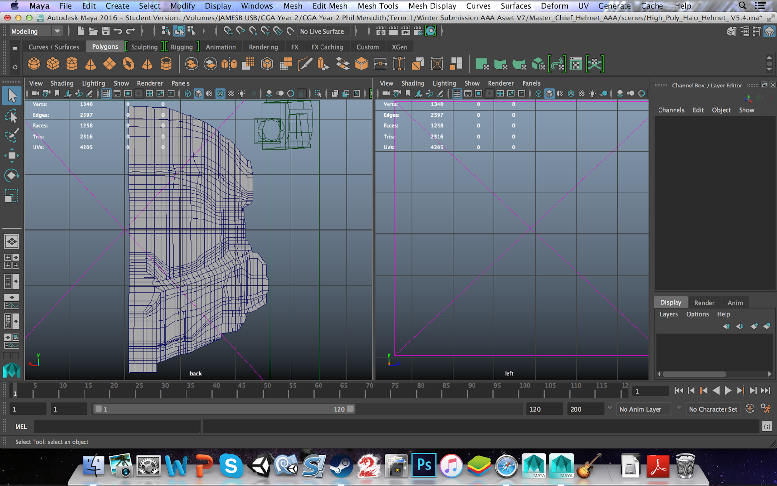
  (Figure 5)
Having added the new edge loops I then moved the vert's into appropriate positions in accordance with the reference model so that I could begin pulling out the shape.

  (Figure 6)
At this point it was pointed out to me that it would have been better, for myself and my workflow, for me to have started pulling out the shape of the helmet as I was using the Quad Draw tool. I chose to continue with what I had made due to the time it took me to get to this point, so to help start forming the shape I extracted the faces of the visor and using the soft select tool I began to pull rows of vert's to create the curvature of the visor.
The soft select tool allows me to manipulate objects with falloff. Falloff is the area around the selected components which will also be affected by any transforms I may make despite not selecting those components specifically. This allowed me to make a more uniform curve with the visor.

  (Figure 7)
With the visor shaped out from the initial model I extracted the flat strip surrounding the visor. But due to the visor being moved out of it's initial position with modifications I needed to move the strip back into it's proper position around the visor. To do this I snapped the vert's of the strip to the corresponding vert's on the visor and in the side view straitened the edge loops of the strip to be vertical.

 (Figure 8)
I continued to extract selected faces to pull them out of the model; however judging by the speed it was taking me to sort out the shape of this model, and with the back half still to make, I decided to speak to my assessor for this submission about changing the model I would make for the submission. He was ok with it once I found a reference image and an image of a real life version of the object. That process shall be documented in another blog post.

I was confident I could make this model but I knew I wasn't going to be able to complete the model in time for our first milestone, which was to have the high poly model finished.
To improve I would build this model different; I would start by making it low poly and adding edge loops to define the shape as I go along rather than make the model high poly right for the start and model from there. It's easier to model and low poly model into a high poly model than it is to reduce a high poly model to a low poly model.

Sunday, 5 April 2015

Doctor Who Art

So after a sudden burst of love over Doctor Who, as I normally have over things I love, I decided to make some fan-art of Doctor Who for myself and also as a birthday present for my cousin.


I lost myself in making this so I can't give an accurate build time but I reckon this took me around 8 hours to make (although it did not feel like it) the majority last night and finishing touches this morning.
The image is based off Matt Smith's 11th incarnation of the Doctor with regeneration energy flowing out of his head. I am really proud of this image and the only thing I would do to improve it would be to make his head a bit more visible underneath the glow, I even got the official Doctor Who font to type out the quote.

Friday, 27 March 2015

Term 2: Personal Work

During my spare time I have been trying to do my own personal projects, one of which is this. It's not complete and in recent weeks I haven't had the time to work on it due to deadlines and work, but I thought I would blog this as a work in progress. So far I like it and I feel as though I caught the expression I wanted rather well and I also like the shading around the nose, it adds a lot more depth to the figure than if I had left it bland.


Thursday, 26 March 2015

Project Flyer Shooter: Ewan Armstrong Game Group Project


For the Spring submission in the Games Encounters unit we have been tasked with creating a video game within the Unity engine. We set about getting into groups of 3-4 people and were given the specifics of the game.
Our game MUST include:

        1. High Score 
             2. Splash Screen 
   3. Enemies
4. Flying 
   5. Shooting

Before we set-up the jobs of each member we all began making our now concepts for each piece, I mainly did concepts for the player ship and environment.


This was just a series of quick sketches for the ship and I asked the others for their opinions on which model I should develop on.


In the end I came up with this preliminary sketch of the player ship, although this wasn't used once Jason took the job of designing the ship the final model has some aspects of this design in it, namely the "hover" jets protruding from the side.


These sketches were preliminary sketches of what the environment could be like complete with obstacles. In the beginning we had intended to make the map circular and the player would loop all around as the Infinite Runner but when it came to coding it we realised it was beyond our level to make so we had to scale it back.

My job for the project was the lead Environment artist and for this I created a few concepts for our game using Mudbox and Photoshop. We new we wanted the environment to be based off a valley/canyon, so to get a clear view for concepts I created my own mood board. 


I then set about creating concept pieces for the environment and having been taught how to use Mudbox recently I decided that to better present my concepts I would model them in Mudbox.

Model 1.

Model 2.

Model 3.

I really like how these came out for the environment and so did the others but we all decided that the art direction we wanted to go towards for the final model was with the first model. I then decided to make a concept piece in Photoshop.


At this point the one sheet was put together by Jason that featured art from all of us and a brief description of our game co-written by myself, Jason and Alex.


We then got started on the modelling stage of our project, being the lead environment artist I created all the models for the environment. The initial plan was to have a game where 3 or 4 models would be instantiated in the scene randomly and this would repeat to create the infinite runner aspect whilst changing the environment so that it isn't constantly repeating the same models in the same pattern. So for this I created 3 separate models for the environment, asking for the opinions of the other members of my group before modelling the next. Each are at the same dimensions and start and end at the same point so that they could transition from one to the other without noticing any breaks in the models.

Figure 1:
 Figure 2:

In the end we decided on focusing on one environment model for the final piece and we all decided on Figure 2.

Figure 3:

We decided that to make the world space a little less dull and as a game mechanic we would include obstacles for the player to avoid that once collided with would either damage you or completely destroy you. For this I looked at references of plateau's and rock stacks but decided to model our obstacles after this image:


and so we had our obstacles a pair of rock stacks. To make the models flow more naturally and feel a little less man made I imported the Maya file into Mudbox and played around with the sculpt tools to round out the edges and make them a bit more random in design as well. I like how they came out and I also like the design of them thinning out towards the top where they have eroded by the wind and other sources.


Jason created an animation that would be played once the player starts the game and would lead directly into the game itself. He asked me to create some scenery based around boulders and so (with Jason's input) I made this pile of rocks and boulders. They were not textured in Mudbox like the other models I made but instead had a simple material attached to them inside Unity.


With my models finished I went into Mudbox with the rock stack model's and and the chosen environment model and began texturing them. 


First off were the rock stack's, I like the outcome of these textures they have the rock feel I was going for and their coloration is spent on to what we were going for in tees of our game's aesthetics. One downside of these textures however is that the models are fairly low poly, which in some respects is good as they have smaller file sizes making it easier for the game to spawn them in however it also means that I had fewer vertices to play with when texturing in Mudbox.
In Mudbox the level of detail one could apply to a model is influenced by the vertices count and thus when I tried to paint with stamps and stencils very little actually came out of them, regardless I still feel these models came out well.


Secondly I textured the environment model, but before that I used the sculpt tools of Mudbox to make the model feel more natural and look less man-made than it had appeared to be when I modelled it in Maya. One way I did this was by using the sculpt tool to lower the centre of the canyon bed, this made it appear as though the canyon was carved out not only by glacier (as is most likely) but also that a river once flowed through the canyon and has since dried up. Because of this aspect I also textured the canyon bed with some green to make it appear as though foliage is growing there due to the fertile soil, but the rest of the model was textured to be dry and barren hence the darker shades of brown. 
I think this came out really well, again like with the rock stacks I had a little issue with the low number of vertices to play with whilst sculpting and texturing but I like it and so did the others.


And here is the model put together with the rock stacks in place in relation to the environment model. All there was left to do know was to export the models as an FBX file for use in Unity.


With the model stage complete I could move onto scripting and the most important script I contributed to this game was the Infinite Runner script. A script where my environment models would be instantiated in the scene and translated behind the player, creating the illusion of the player moving forward. 
This script in particular creates a private list of the instantiated prefab's the first being called "first road" and the last being called "last road" when "first road" is translate to a certain position behind the player (in this case: if(first Road.position.z <- 50f) ) first road is taken out of the private list,  is destroyed, the next prefab along becomes the new first road and a new "road" is instantiated where last road was initially instantiated and this repeats.


With the Infinite Runner complete I moved on to creating the script for the player. This script includes a boundary that prevents the player from going to far up, down, left and right, includes code that allows the player to move on the X-axis and Y-axis and instantiate and shoot a bullet prefab.


Another script I made was a simple script, it was simply On trigger enter destroy game object. This was attached to a cube without a mesh collider which was a child of the player model, this meant it stayed with the player. The function of the script is to destroy any and all game objects which pass through it, namely the enemy clones that aren't killed and the enemy bullet clones.


This was my final script for the game which had some use in the final game, it instantiates an explosion prefab upon collision with the player and was designed to destroy both the player and enemy that collided with the player. It was not used but the enemy explosion prefab instantiate was used in a separate script, final script for the enemy prefab.

Term 2: Maya Session 8 and Assessment

This is our assessment task for our second term at UCA, we have been tasked with modelling an adolescent male with the assistance of turnaround concepts. We were provided with a previously set-up Maya project with the front and side view concepts of the character already in place and a mirrored cube in position to begin working on. 

I began with the feet, adding edge loops with the Insert Edge Loop tool sparingly (as and when I need it) so as to reduce the total number of triangles on the mesh, as per the brief we were provided we are to aim for around 8,000 triangles on the mesh.


The second image of each stage is the model as seen in a smooth view (3 on the keyboard)


From here I extruded the edges and scaled them in, once in position I extruded the edges again to start making the calves of the legs. The initial extrusion was to make the shape of the shoe which is a little thicker than the ankle.


Next I extruded the top edge of the leg above, pulled it up and extruded the edge again, scaled the edge out and once again extruded but now I pulled it back down to be level with the top of the leg I made above. This created the inside of the shorts and I could then extrude the edge out again to create the thin edges of the shorts and I could start to extrude up to create the thighs.


The next few images show an incorrect geometry for the groin of the model so after finishing the base model I went back to the groin to sort out the geometry where the edges coming up from the legs curve around and meet at the groin. This is so that during the rigging process after the model has been finished the geometry can be deformed accurately to how the human body moves in real life.


Here I began to pull the vertices of the thigh up so that an edge loop from the groin would rise up over the hip and back down around the back, this was done as the reference images of the human mesh show the edge loops/vertices rising around the thigh.


With the torso I continued the model until I got to the shoulders, at which point I used the scale tool to pull the vertices in to create the edge loops that circle the neck. But due to the model being mirrored instead of being one complete mesh at this point I had to pull the vertices in the middle at the separation so that I could merge the vertices later on.


To create the head I used a technique Robin showed us in class, create a poly cube and smooth it twice, this adds edge loops to the cube and turns it into a sphere shape. However the trick is the edge loops are now exactly how a human head mesh should be, radiating out in circles from ear to ear. Once the head and the hands were complete I combined the 2 halves of the model and merged all the vertices along the central split. After that I smoothed the model to 1 subdivision, creating a more organic model but raising the Tri count to over 8,000. 
So I started to remove unnecessary edged loops to reduce the Tri count eventually stop once I reached   just over 7,000.


Next I set about laying out the UV maps, I did this by (for example) selecting half the faces of the Torso, making a planar map of those faces and unfolding them. I would then repeat this for the other half of the faces; then I would select the edges that I didn't want to be exposed and used the Move and Sew UV edges tool, this connected my 2 planar maps for the torso and I could then unfold them again. Above in the UV texture editor image on the bottom left hand corner is my Planar map for the torso of my model.

With the Planar maps set and laid out to optimise the space I could move onto texturing, to do this I took a UV snapshot of the UV texture editor and saved it as a TGA file which I opened up in Photoshop to begin painting the textures on.


I made use of Photoshop to texture as I could copy the symbol on the chest of the reference image and place directly onto the model without hassle of making it from scratch.


And here is my finished model, I am really happy with how this turned out, I applied all the textures needed and they too came out well. The things I would improve on next time would be working on those laces as they were a hassle to paint on and if given the chance I would try to add some more edge loops onto the face as I wasn't able to shape the face in detail and that can be noticeable. But I believe I did well on this and look forward for more.

Something to note as an after thought, whilst looking at the previous versions I saved for security I realised that the geometry on the head was better. At some point after smoothing the model and trying to reduce the total number of Tris to below 8,000 I seem to have deleted an edge loop on the face, which is why I find the chin (at least) to be a bit off, unfortunate but I still like the outcome.