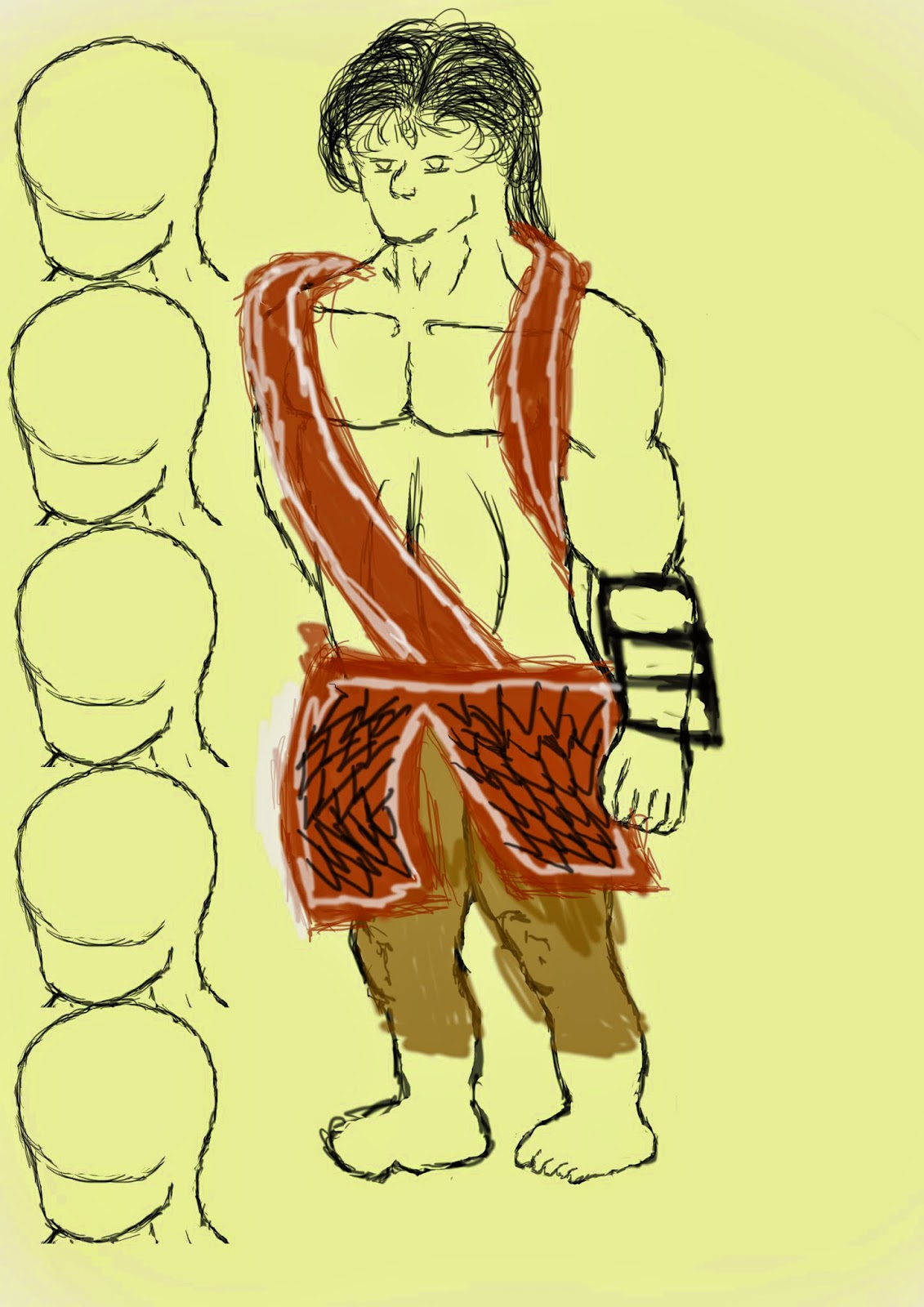
This is our ongoing project, due to be completed for the 12th December. The aim of the project is to utilize the skills we have been learning in Maya throughout our sessions to recreate the building in the picture above (which I shall refer to as the Sample Image). I shall be working in Inches for this project.

This is the cylindrical column made in Maya, with a Human reference stood next to it. The column itself is 197 inches tall, which is the average height from the ground floor to the ceiling of the floor above, although I set the height to 200 for easier modelling. To create the first extrusion along the column I simply set the subdivisions height to 20 and using my eye to judge the distance highlighted one strip of faces on the polygon. From there I used the scale tool to pull out the shape and once that was complete I selected the edges of the, what was then a flat cylinder, extrusion and applied a bevel to create the curved shape. I did the same for the other extrusions, except for the top 2 I simply left them in their cube like shapes.

For the skirt along the base of the wall I began making a simply poly cube.Again in inches I set the dimensions to 40 wide, 40 high and a depth of 5 and also set the subdivisions depth and width to 10 and the height to 20. Using the face selection tool I removed all the faces along the first subdivision layer along the front of the cube and removed about half of the faces along the top. I then extruded the edges and used the fill hole tool to create the 90 degree angle seen on the top of the polygon.
I then entered Vertex mode (a vertex is shown as a spot on every single corner point) and entered the right view. From this view I could highlight a whole row of vertex's without hassle to manipulate the shape into a curve as seen above.
Finally, similar to my first step, I selected the bottom 2 rows of faces on the front side and used the extrude tool to pull them out of the object, creating the "foot" appearance at the base.
At the front of the building is a different design of a support column. The whole object was made using a single cube polygon and the extrude tool.
Following the sample image I cut into the face of the wall and wall skirt (on the fourth wall along) the shape of of door. Using this template I created a poly cube to fit the space I had created.
With my door size finalised (5 inches width, 187 inches high and a depth of 100 inches) begun to deform the face of it to create the shape seen in the sample image. In the image the door has 3 inlets up the centre with the top one being longer that the other 2. For this I created a subdivisions height of 18 and depth of 8. I then selected the faces that would be extruded, to make the inlets I selected 4 faces high for the 2 bottom inlets and 6 high for the top inlet, with all 3 having a width of 4 faces.
Next I selected the 4 faces in the corners and the 4 faces above the first 2 inlets, again I extruded these to create the metallic squares along the door seen in the sample image. To make the centre point I simply switched to Vertex mode and selected the middle vertex on each of the 8 square extrusions, from there I just selected the move tool and pulled them away from the door bringing them all to a point.
This is the roof for the walls of the Chateau. I have yet to adde the decoration to the edges but for now the roof itself is complete. it measures at a length of 2,500 inches, and a width and hight of 200 inches. I made it using a polygon cube, with this cube I removed the top face and flat side faces.
I changed my viewing perspective to the back view which allowed me to see the polygon from the thin, flat side. I turned to vertex mode and selected the top vertexes so that I could deform them with the move tool (shown in the above image). I moulded them into the triangular shape of the roof and selected the top edges, from here I used the bridge tool to fill in the space between the 2 edges and I used the fill hole tool to fill in the empty space on the flat sides.
I have now put together everything I have done thus far (excluding the from support column) into the side wall you can see in the sample image. With a little tweaking I can make the other 3 walls and that will be part 1 complete, part 2 will incorporate the second story and front porch whilst part 3 shall be the final structure in the centre courtyard.
With one side of the base of the temple laid down I used the Mirror Cut tool to create a corner piece on the roof. What the mirror cut tool does is it creates a duplicate of the object the tool is being used on
I continued to use the Mirror Cut tool on both the wall skirts and walls themselves to continue the courtyard border.
With one half of the courtyard complete using the Mirror Cut tool I could now use the Mirror Geometry tool, which allowed me to mirror the polygons I had already created to make one half of the courtyard, and merge them together to complete the courtyard shape as seen above.
This is the courtyard complete, and now onto the front porch and central temple.
I began by duplicating the original base I used and scaling it down into a rectangular shape for use as the floor in front of the courtyard. I then imported the redesigned support column and placed them at equal distances apart with 4 in a row, making the supports for the extended roof. I also created a polygonal cube as a placeholder for the central temple, and also using the Align tool to place it in the centre of the courtyard.
Moving on I imported the Roof I had built again and scaled it to fit over the support columns and resemble the first floor Roof in the sample image. I then imported the Roof again as the Roof I had placed previously has 2 extensions as seen in the sample image, so by importing just one more Roof I could scale it to size by eye, place it in it's appropriate place, duplicate it and (utilising the Move tool) moved it across to mirror the original (I utilised the front view to get a good sight on the symmetry).
I decided to move away from the front part of the chateau and begin modelling the central temple. I started by scaling the height by eye, using the sample image for comparison. I then added 16 subdivisions to the height, I chose an even number for symmetry and because 16 added the right distance between the divisions from top to bottom.
Selecting the bottom 3 subdivision faces I used the Extrude tool creating a new set of faces for me to deform, all of which were connected like a cube. I switched to the Scale tool and scaled in all directions evenly by selecting and holding the centre axis cube, this was how created the extension at the base.
Next, going up the subdivision faces in sequence, I proceeded to repeat my actions to create the base but I made sure to make the extension smaller than the base so as to follow the sample image and then each extension above progressively got larger and larger to create this reverse staircase effect.
In the sample image the central temple has it's own design of wall skirt so I made that to fit onto the model I had built at the time and above was the result.
I then proceeded to use the Mirror cut tool to create the corner pieces of the new wall skirt for the central temple and wrap the skirt around the geometry. I also duplicated the door I had made and placed it in the centre of the central temple just above the wall skirt as the image does depict a door in that spot.
Upon the placement of the door on the central temple I used the Insert Edge Loop tool to cut some edges into the wall skirt and deleted the faces to create the geometry at the front of the chateau so that I could fit another door there. Although I cannot see a door in the sample image in this spot I placed it here on intuition as other wise there would be no way to enter the building.

Back to the central temple and I began to create (what appeared to be) a wooden support structure wrapped around the structure where the door is positioned. For this I made a polygon cube and set the diameter to 4 inches, length to 200 inches and the width to 20 inches. I placed my first on top of the wall skirt I had placed previously and duplicated the thin cube, moved it up (judging the distance by eye from the sample image provided) and used the Shift D function which duplicated the panel again and placed it the same distance above the one below as I had set with the first duplication. I did this until there were a total of 12 panels up the wall.
Here I duplicated one of the panels and changed the diameter to 20 to make the panel a thin cuboid, this would be used to mark out the 4 corner struts, the 4 between them on the longer sides and the 2 either side of the door mirrored on the front of the temple and back.
After the wooden structure was complete I went ahead and created the Roof piece for the central temple. I used a poly cube to make this and I simply went into Vertex mode, selected the corner Vertex's on the base corners and used the Scale tool to equal stretch the corers to create a Trapezoid shape as depicted in the sample image.
Like with the front door which I could not directly see but made an educated guess that there would be one, I added a flight of stairs in front of the central temple. I did this as the sample image depicts there being a door however the second floor structure in front blocks our view of what is in front of the central temple, and yet with a door being so high up one would presume there would be a way to reach said door which is why I created a flight of stairs for my chateau.
Leaving the central temple for a bit to work on the other structures I had yet to implement I began work on the second floor. For this I simply duplicated the original cylindrical column and moved it up, from here I duplicated it again and used my eye to judge the distance between the 2 columns from the sample image. Again I duplicated them both and moved them down the other end and used the Align tool to place the columns down the other end of the image above in the same position as the original 2.
With the four corners in place with the columns I imported the wall I made at the start and scaled it to the length between the columns as seen in the above image. I then used the Mirror cut tool to create the corners of the walls and to make a square shape with them, after this photo I used the Mirror geometry tool to finish the 4 walls.

Before I had the extension already built into this Roof (the one situated above the front door) however I decided I could make it work better using the Roof I modelled for the central temple. So what I did here was to re-import the original Roof model and deform and scale it like I had done previously just without the extrusion on the front of the model. The change here is that I used the Insert Edge Loop tool to create some edge loops on the polygon surface, the purpose for this was to flatten the middle potion of the roof to create the balcony but to do this and make it in the centre of the roof I needed more faces and to create more faces I inserted edge loops.
I also duplicated 2 of the cube support columns below this Roof model, shrunk them down and placed them on the newly created floor for the balcony (as seen in the image above).
Also I took the Roof model I created for the central temple and deformed it into an elongated shape to create the extension of the roof of the second floor, which sat nicely on my 2 support columns like in the sample image.
I Extruded the flat top surface of the trapezoid roof and took the edges and used the Scale tool to pull them together to create the triangular pointed roof you see towards the top. I then extruded the flat face of the triangle out towards the front of the building to create the extension that can be seen on many of the chateau's roof's including this one. From here I used the Cut Face tool to create 2 diagonal edges parallel to the outside frame, I then selected the face in the centre and extruded it back into the geometry to create the thin strip of tiling extended from the roof like in the sample image.

I made these railings in a similar fashion to the cylindrical support columns as they are very similar in shape and form. Each extension from the base poly pipe was made using the Extrusion tool and similarly with the wood frame on the central temple I used the Shift D function to repeat duplications of the pipes and keep the distance between them equal creating 14 across, the same as in the sample image.
Back to the central temple, the next part I needed to build for it were the wavy pipes that surround the building towards the top like the wooden frame beneath. To make this I used the Non-Linear Bend tool both at the base of the pipe to create the initial curve and again towards the top to crete the exiting curve.
I began applying these wavy pipes to the structure similarly to how I added the wooden frame in that I placed the first in the corner, duplicated and used Shift D to repeat the transform along the side, which produced the structure in the image above.
After adding the pipes 360 degrees around the structure I created the 3 pipe supports which also surround the structure. Again like with other parts of the model I used the Mirror Cut tool to create the corner of the pipe supports and then used the Mirror Geometry tool to complete the other half of the supports.
I created this roof topper for the central temple using 2 polygons a cube and a pipe. I deformed the pipe like I did the railings and cylindrical support column to create the spike ornament you see before you and I centred it on the cube as a pedestal.
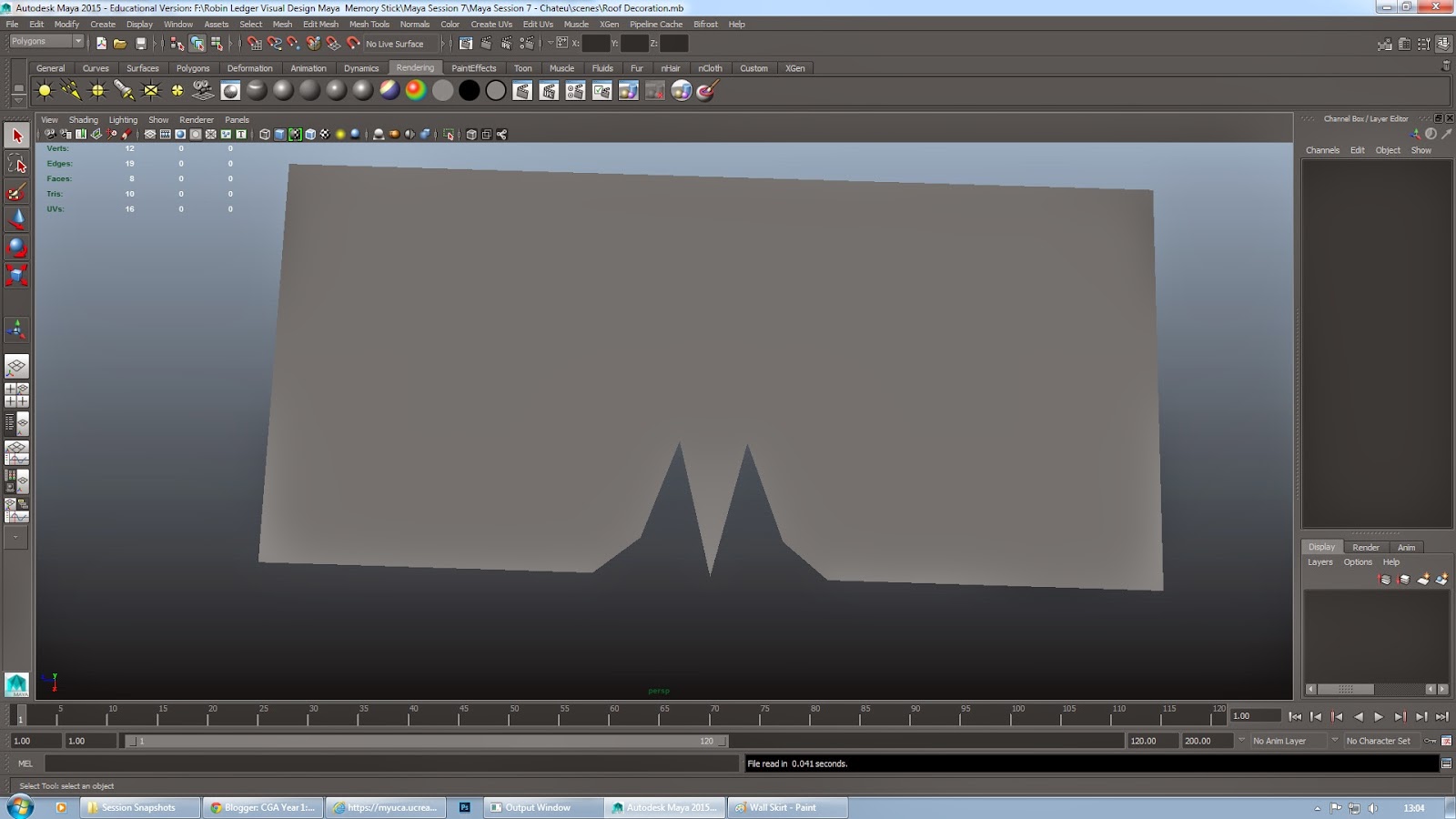
In the sample image the roof's have decorations, this is what I made for those decorations. Here it is quite flat but in the final model I transformed the Vertex's to create a circular shape in the corners.
With the Roof Decoration model complete I imported it into the scene and positioned just one on the corner of each roof. I then Duplicated and used the Shift D function on the model to make up the distance of the roof edges they are attached to. To make the model flow around the corners I once again used the Mirror Cut tool which allowed me to create 90 degree corners wherever appropriate.
My next goal, considering the other main decoration of the chateau had now been applied to the model, was to create (what appear to be) bangles made of a wooden material most likely that hang off the extensions on the roof above the front door.
For this I made a poly cube and altered it's dimensions to a depth of 4 inches, width of 20 and height of 100 inches. I then increased the amount of subdivisions on the cube to 8 in height and 8 across the flat surface of the cube. This allowed me to manipulate the Vertex's in Vertex mode so as to make a circle piece at the bottom of the cube (as you can see above), more vertex's meant I could alter shape more accurately into a circle.
I imported the model into the scene and scaled to size judging by eye from the sample image, then I applied my duplication method to create an even spacing between the bangles making a total of 18 across.Now that they were in place for one portion of the roof I simply duplicate all of them to retain the distances and scale and rotate them to fit the other roof extensions as seen in the sample image.
Moving back to the central temple I duplicated the trapezoid roof I had built earlier, scaled it up to size for the final roof on the structure and positioned it appropriately. Then like earlier I Extruded the top face up and manipulated the side edges with the Scale tool to create the tapering pint of the roof and I used the Cut Face tool like earlier to create the over hang on the extension.
After importing the Roof Ornaments I had created earlier and positioning them atop the central temple I was finally ready to begin texturing my model. To start with I used Automatic Mapping with the entire model selected to position the faces evenly in the UV texture editor, this made things so much simpler to manipulate as all the separate objects where clearly defined and were in no way hideously deformed.
These where the 2 textures supplied to us for use when we began texturing. All of my model within the scene had these attached to them via a new material known as a Blinn.
Models which only had a colour to them instead of a detailed texture where again made using Blinn's however instead of assigning a file to them (such as I did for the Roof tiles and Brick Tiles) I simply altered their colour to match the models in the sample image.
Mid-way through texturing and I realise that I hadn't created the windows in the model which are quite clear in the sample image. So to create the space where the wooden frames of the windows would sit I used the Insert Edge Loop tool to create more faces for me to manipulate on the walls. I then judged by eye the distance between the frames and kept each frame to the same width and height by deleting 3 faces across for the width and 4 face up for the height, as the sample image shows the frames as being taller than they are wider.

I created the wooden frames by creating a poly cube setting it's dimensions to a width of 4 inches, a depth of 6 and length/height to 120 inches, I then rotated the thin cube on the Z axis 90 degrees to making it lie flat. I used this model of the 4 side of the frame which are a little thicker than the rest of the frames structure, and for the structure between these frames I simply duplicated the original cube, scaled it down and used the Shift D function to create an even space between the individual panels. I then duplicated the entire model a total of 7 times (for the 7 frames I had carved out of the walls) and transformed the object into position in the other frames.


And here is my final Model of the Chateau. I have taken screenshots of the model in the same position as the sample image and form most other angles to show a 360 view of the model. I ma really happy with my work on this model and believe it turned out brilliantly, however there is one thing I notice about the model and that is that the central temple is to large compared to the second floor and that the roof of the second floor is aligned with the central temple.
There are 2 ways I could change this, the first would be to scale down all the models used to create the central temple and realign them in their proper place to match the height of the second floor I have built. Or I could scale up the second floor to match the size of the central temple, however on second thoughts, with that idea yes I would make the second floor in scale with the central temple but then the rest of the structure would not be to scale so that would require a great deal more effort to fix than the first idea.
But as I said overall I am really happy with this model especially with all the time I put into it.